ReAmiga 1200 - donor board becomes problematic
Description
Update to the reamiga I have been working on. I wanted to get more time out of the original board and given it was mostly working, run workbench by setting up an IDE compact flash card.
Having setup the CF card and installing it, i noticed the video was particularly bad on the diagrom and swapping back to the kickstart roms i was getting a black screen. It was okay with the diagroms but the odd CIA was showing issues now (zero ticks) and when i was using the diagroms i recalled the keys were sticking and i suspected this could be related. At the time i thought this was the contacts on the back of the keys but seems more serious problems were at play.
recap
I decided to look into the issues as this was good experience in troubleshooting the architecture and as i said before I wanted more life out of the board, it was time to recap it. You cant measure a capacitor on a circuit you have to remove it to test it but you can do a resistance test to see if its charging. Below is a table of the caps and their ratings when removed. To remove I used 2 soldering irons to lift them off, I am not going to rock them and risk pulling pads, and i still have not got hot air but I am going to order when i get paid! To give room to work i left the 3 through hole caps (1000uF, 470uF) until last around the RF modulator.
farad scale:
- 1 mF (millifarad, one thousandth (10−3) of a farad) = 0.001 F = 1000 μF = 1000000 nF
- 1 μF (microfarad, one millionth (10−6) of a farad) = 0.000 001 F = 1000 nF = 1000000 pF
- 1 nF (nanofarad, one billionth (10−9) of a farad) = 0.001 μF = 1000 pF
- 1 pF (picofarad, one trillionth (10−12) of a farad)
actual ratings of old capacitors when removed from board:
| position | expected | actual |
|---|---|---|
| C822 | 47uF | 47uF |
| C305 | 10uF | 10uF |
| C303 | 22uF | NA |
| C304 | 22uF | NA |
| C334 | 22uF | NA |
| C324 | 22uF | NA |
| C407 | 10uF | NA |
| C239 | 100uF | POP! |
| C236 | 100uF | 97uF |
| C409 | 100uF | 105uF |
| C235 | 100uF | 112uF |
| C459 | 22uF | 23uF |
| C21 | 10uF | NA |
| C821 | 47uF | 48uF |
| C307 | 470uF | 488uF |
| C408 | 1000uF | 914uF |
| C237 | 470uF | 485uF |
| C811 | 1000uF | 948uF |
C239 was exciting it popped when removed ! As you can see almost all the smaller rated 22 and 10 were not working at all and most likely leaked onto the board corroding it. Ive since found that most of the caps are related to audio/video and board will function even if they are all dead or even removed.
No more blue
Having replaced all the caps taking care not to damage the board, i had the unusual issue of only red and green on screen. At first i thought i might have made a mistake but having rechecked my work i saw no issues. I also could not see any solder that had dropped and shorted anywhere. At this point i got the PCB explorer and schematics up and started to work through causes of loss of blue. The RGB signals begin at Lisa (display controller), pass through the video DAC, onto the composite encoder ending at the RF modulator / TV.
I did not have a composite cable to check the separate video output channels all i had to work with was the RF for now. I covered everything and it was confusing, the resistors all checked out and continuity, but one thing seemed strange, the signal to the video encoder.
I took a logic probe to the RGB outputs on the video DAC and RG had signals, B also did, so the video DAC is outputting on the blue channel. Looking at the encoder inputs the RG were fine but the B was dead. So time for a very close look at the circuit between them.
In the schematics there is only one component between them a 0.22uF capacitor at C213 on the back of the board. Continuity from the encoder to positive on C213 was good, so no broken trace here. From the video DAC output to C213 was dead, there was a broken trace here! Eventually i pinned it down to a trace about 1 inch long traversing many layers of the board, immediately after C213 running to the video DAC.
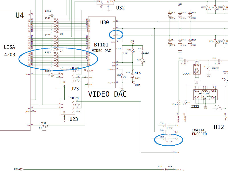
Above you can see the blue output signal from U4 Lisa, to U30 the video DAC. Blue output from the DAC on pin 24 is input on pin 4 on U12 the composite encoder. The last trace inch of the trace from pin24 on the DAC to capacitor C213 was at fault.
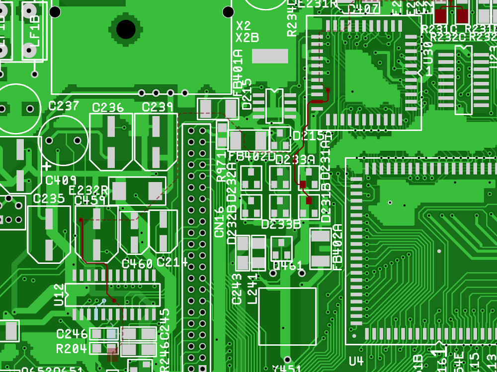
Above trace in red running on the top layer (solid red line) past capacitor at C459 at fault.
Fix
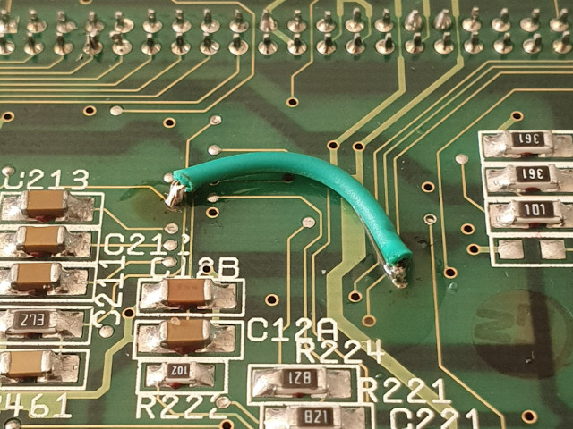
Above shows bottom of the board where a wire bridges broken trace on top layer using the through holes. An experienced professional would have repaired the actual trace on the top of the board.
what happened ?
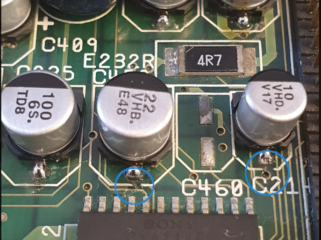
Cap C459 is directly over the trace that has gone, i do not recall anything about that area but looking on the top i realised this is a surface trace and the board its cut. I did not notice this but the screen print of the capacitor on the board is directly over the trace, while cleaning the board the screen prints have come off in a lot of places and the one over the trace ( also C21 to the right ) has come loose potentially taking the trace with it. The pad for C459 positive side also looks heavily corroded.
When replacing the capacitors i used a hakko iron and a cheaper older iron i had spare. The old one is generic and has an old tip, it feels like it has a sharpness to it and potentially also broke the trace.
Good thing this wont be an issue on the reamiga board with the new layout! Ive also noticed the through whole capacitors have been moved to more conveinient positions for easier maintenance, as i said earlier the through holes are tight to the surface mount making them hard to work with.
lessons
Get a better second iron or ideally hot air! I know i was using my hakko in the left hand so my right was using a cheap age old iron with a not so good tip which is clearly a risk to traces
Black screen at boot
https://retrocomputerverzamelaar.nl/commodore-amiga-problems/
The black screen could be a few things, given i know keyboard and odd CIA have issues in diagroms i am going to focus on them.
U13 Keyboard controller (left above budgie 391425)
U7 - ‘Odd’ CIA functions: parallel port, keyboard, some floppy support, joystick/mouse button number one.
First i tried holding them down for cracked solder joints, this had no effect so the simple fix of re-flowing is probably wrong. I could not find any reference to like for like issues so next steps is to troubleshoot everything looking for faults.
I opened up the PCB explorer and followed everything from the keyboard header, U13 and U7. My reasoning was there maybe more than one issue and might as well check everything.
I found resistor at R628 rated 1mO reads 0.888 and climbs, R511A and R511B both rated 10kO read between 1.5/1.6 then i found U7 CIA pin 42 (RS0 A_8) had no continuity. This pin is wired into a lot of the board including the kickstart roms. Its function described as ‘The address inputs select the internal registers as described by the Register Map’.
The trace is corroded along the way and hard to bridge as with previous fix. I could not see where the break was so scraped to expose the trace and tested along the length of the trace. Doing this i found it was broken immediately after the pad. I could not see this even with magnifier, or zoom with video on camera phone. Knowing continuity was clearly working up to this point i decided to bridge from the pad with solder, this took more than 1 attempt to bridge by dragging solder but connection was made and i got continuity from the pad! Results below.
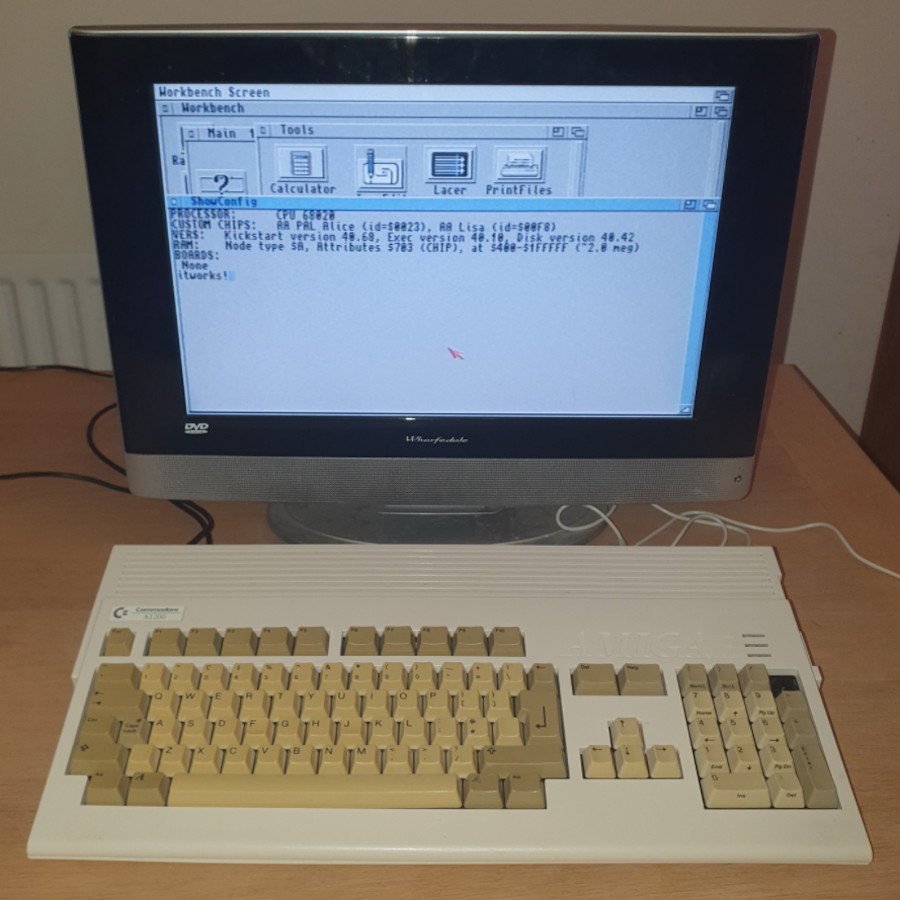
Yes, that is workbench 3.1! And so far its completely stable, running for hours at a time.
References
PCB Explorers : http://amigapcb.org/
Schematics: https://www.amigawiki.org/dnl/schematics/A1200_R1.pdf